
Instrument gauge valves isolate a pressure gauge, switch or transmitter from the process and allow trapped pressure to be vented, so the instrument can be removed, tested or calibrated safely. TSI sources gauge valves against your specification (valve type, body material, seat and packing, end connections, pressure, temperature and documentation) through qualified manufacturers and stockists.
Values are representative ranges across comparable manufacturer series, not the combined rating of one valve. Maximum pressure, maximum temperature and flow capacity are not simultaneous ratings. Standard designs are typically rated up to 6,000 psig and selected designs up to 10,000 psig; soft seats limit the rating well below the body. Exact ratings are confirmed against the selected size, material, seat, packing and end connections.
Not limited to the items shown. The four designs below are representative of the range, not a fixed list. Models, sizes, connections, pressure ratings, body materials and alloys vary by manufacturer and by order. Send your specification and drawing: TSI reviews it technically, sources the gauge valve that meets it, and confirms the model, size, pressure rating and material in the quotation. Items outside the four designs shown are handled the same way.
Images on this page are representative illustrations of each product type, not photographs of supplied items.
Which gauge valve?
| Requirement | Choose | Code |
|---|---|---|
| Isolate a gauge and keep a second instrument, test or vent connection | Multi-port needle gauge valve | TSI-12-001 |
| The same function on an insulated line | Extended (lagging) body | TSI-12-002 |
| Isolate, then vent or drain the trapped pressure before removing the instrument | Gauge isolation valve with vent / bleed | TSI-12-003 |
| Dirty, viscous or blocking medium where the flow path may need rodding | Rising-plug gauge valve, soft seat | TSI-12-004 |
| Two valves in one body (block and bleed), manifolds, or double isolation | Not a gauge valve: enquire separately | — |
Range at a glance
| Code | Type | Process inlet | Outlet and ports | Max. pressure at 100°F | Temperature | Seat / tip | Body material | Orifice |
|---|---|---|---|---|---|---|---|---|
| TSI-12-001 | Multi-port needle, standard body | 1/2 or 3/4 in. male NPT | 1/2 in. female NPT outlet; two 1/2 in. female NPT gauge ports | 6,000 psig (414 bar); 10,000 psig on selected designs | -65°F to 450°F (PTFE); graphite to 1,000°F on selected designs | Metal-to-metal, vee or ball tip | 316 / 316L; alloys on request | Approx. 4.0 to 6.4 mm |
| TSI-12-002 | Multi-port needle, extended (lagging) body | 1/2 or 3/4 in. male NPT on extended inlet | 1/2 in. female NPT outlet; two 1/2 in. female NPT gauge ports | As standard body | As standard body | Metal-to-metal, vee or ball tip | 316 / 316L; alloys on request | Approx. 4.0 to 6.4 mm |
| TSI-12-003 | Gauge isolation with vent / bleed | 1/2 in. NPT (1/4 in. on some ranges) | 1/2 in. outlet; 1/4 in. vent or bleed port | 6,000 psig (414 bar); 10,000 psig on selected designs | -65°F to 450°F (PTFE); graphite to 1,000°F on selected designs | Metal-to-metal; PEEK soft tip on selected designs | 316 / 316L; alloys on request | Approx. 4.0 to 5.4 mm |
| TSI-12-004 | Rising-plug, soft seat, roddable | 1/2 or 3/4 in. male NPT | 1/2 in. female NPT outlet; two 1/2 in. female NPT gauge ports | Up to 6,000 psig on selected seat and body combinations; seat-limited | Seat-limited: acetal to 250°F; PEEK to 450°F or higher on some designs | Replaceable soft seat: acetal, PFA or PEEK | 316 / 316L; Alloy 400 on selected ranges | Approx. 6.4 mm (0.25 in.) on 1/2 in. designs |
Family ranges for comparison only, not simultaneous ratings. Exact pressure, temperature and flow are confirmed against the selected model, size, material, seat, packing and end connections.
AMulti-Port Needle Gauge Valves
A single needle stem isolates the instrument from the process. In addition to the instrument outlet, two further 1/2 in. female ports let you fit a second gauge, a pressure switch or transmitter, a test or calibration connection, or a vent. The body is machined from bar stock with a non-rotating stem tip, so the seat is not twisted as the valve closes.
Family reference data: pressure, temperature, sizes, materials and testing
| Working pressure | Up to 6,000 psig (414 bar) at 100°F (38°C) in 316 stainless steel; selected designs are rated 10,000 psig (690 bar). Rating falls as temperature rises (see the pressure – temperature table). Alloy 400 bodies are typically rated 5,000 psig at 100°F. Exact rating is confirmed by manufacturer and configuration. |
|---|---|
| Temperature | -65°F to 450°F (-54°C to 232°C) with PTFE packing; flexible graphite packing to 1,000°F (538°C) on selected designs, and higher on some. Soft-seat (PCTFE) tips are limited to 200°F (93°C). |
| Size | Process inlet 1/2 in. or 3/4 in. male NPT; instrument outlet 1/2 in. female NPT; two gauge ports 1/2 in. female NPT. Female inlet versions on some ranges. |
| Body material | 316 / 316L stainless steel; Alloy 400, Alloy C-276 and super duplex on request, by model |
| Stem tip and packing | Non-rotating metal vee or ball tip; PTFE (standard) or flexible graphite packing; PEEK or UHMWPE packing on selected designs. Cobalt-alloy tips on selected designs. |
| Orifice / Cv | Approx. 4.0 mm to 6.4 mm (0.16 in. to 0.25 in.) depending on design; Cv approx. 0.35 to 0.86 where published. End connections can restrict flow below the valve Cv. |
| Ports | One process inlet, one instrument outlet and two gauge ports (three outlet connections). Ports are normally supplied open; plugs and bleed valves are ordered separately or fitted on request. |
| Testing | Valves are factory tested by the manufacturer; test pressure, leakage criterion and certificates are confirmed per order. |
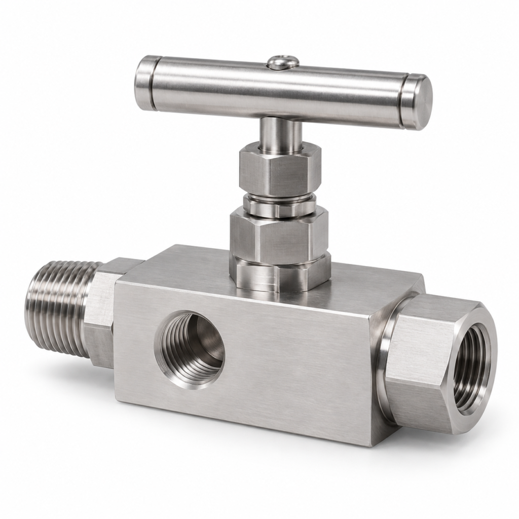
Representative image — the item supplied is sourced to the approved drawing and specification, confirmed at order.
TSI-12-001Multi-Port Needle Gauge Valve, Standard Body
Bar-stock needle valve with a short threaded inlet. Isolates a gauge or transmitter and provides two additional 1/2 in. female ports for a second instrument, test connection or vent.
| Size | Inlet 1/2 in. or 3/4 in. male NPT; outlet 1/2 in. female NPT; two 1/2 in. female NPT gauge ports (reference: 1/2 in. male x 1/2 in. female) |
|---|---|
| Pressure | Up to 6,000 psig (414 bar) at 100°F (38°C) in 316 stainless steel; selected designs 10,000 psig (690 bar). Derates with temperature |
| Temperature | -65°F to 450°F (-54°C to 232°C) with PTFE packing; graphite packing to 1,000°F (538°C) on selected designs |
| Body material | 316 / 316L stainless steel; other alloys on request |
| Orifice / Cv | Approx. 4.0 mm to 6.4 mm; Cv approx. 0.35 to 0.86 where published |
| Length | Approx. 136 to 137 mm (5.4 in.) overall on the reference 1/2 in. designs |
| Tip / packing | Non-rotating vee or ball tip; PTFE or graphite packing |
| Handle | Straight bar (T) handle |
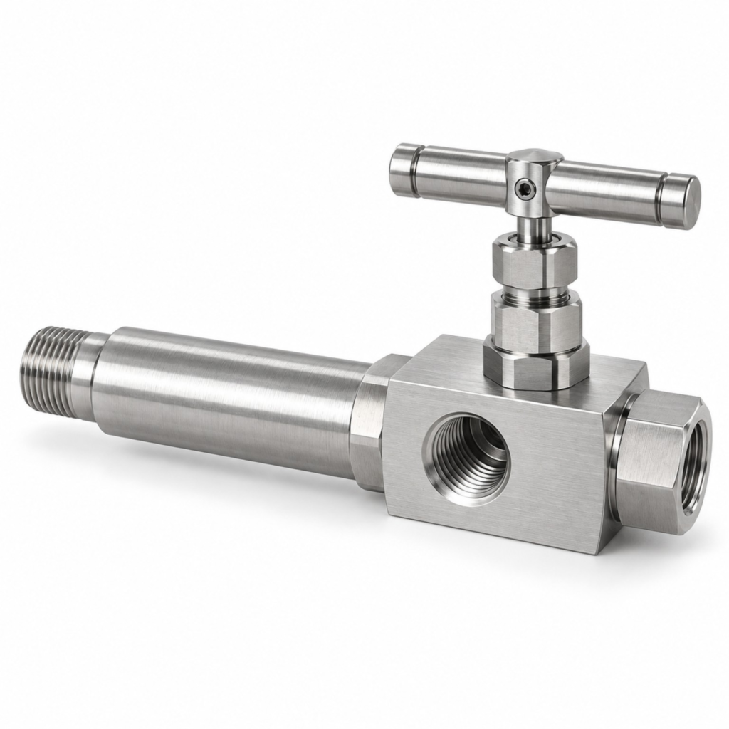
Representative image — the item supplied is sourced to the approved drawing and specification, confirmed at order.
TSI-12-002Multi-Port Needle Gauge Valve, Extended (Lagging) Body
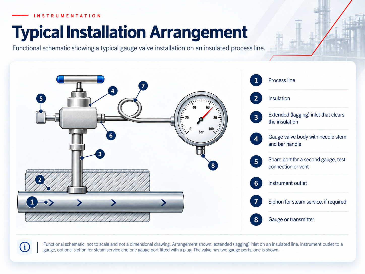
The same multi-port valve with a longer inlet section, so the body and handle sit clear of pipe insulation or cladding. Pressure boundary, seat and packing follow the standard-body design class; only the geometry changes.
| Size | Inlet 1/2 in. or 3/4 in. male NPT on an extended inlet; outlet 1/2 in. female NPT; two 1/2 in. female NPT gauge ports |
|---|---|
| Extension | Overall length approx. 184 mm (7.25 in.) on the reference 1/2 in. designs, about 48 mm (1.9 in.) longer than the standard body; longer extensions are available by design. State the insulation thickness in your enquiry |
| Pressure | Same design class as the standard body: up to 6,000 psig (414 bar) at 100°F in 316 stainless steel; the extension does not raise the rating |
| Temperature | -65°F to 450°F (-54°C to 232°C) with PTFE packing; graphite packing on selected designs |
| Body material | 316 / 316L stainless steel; other alloys on request |
| Orifice / Cv | As standard body, by design |
| Tip / packing | Non-rotating vee or ball tip; PTFE or graphite packing |
| Handle | Straight bar (T) handle |
BGauge Isolation Valves with Vent / Bleed
A single needle stem isolates the instrument, and a 1/4 in. port in the body is opened to vent or drain the pressure trapped between the valve and the instrument. Used before an instrument is removed, tested or calibrated. One vent port is not a second isolation barrier, so this is not a double block and bleed arrangement.
Family reference data: pressure, temperature, sizes, materials and testing
| Working pressure | Up to 6,000 psig (414 bar) at 100°F (38°C) in 316 stainless steel; selected designs 10,000 psig (690 bar). Exact rating is confirmed by manufacturer and configuration. |
|---|---|
| Temperature | PTFE packing typically to 450°F (232°C); graphite packing on selected designs to 1,000°F (538°C). PEEK soft tip to 400°F (204°C) on selected designs; graphite packing and PEEK tip are not available together. |
| Size and ports | Inlet and outlet 1/2 in. NPT (male x female, female x female or male x male by range; 1/4 in. NPT on some ranges); one 1/4 in. female NPT vent port, or a 1/4 in. UNF bleed screw on some designs. |
| Vent function | The port is opened after isolation to relieve trapped pressure. It is supplied open or with a blank plug or bleed plug. Discharge must be routed to a safe location. |
| Body material | 316 / 316L stainless steel; other alloys on request, by model |
| Orifice / Cv | Approx. 4.0 mm to 5.4 mm; Cv approx. 0.35 to 0.46 where published |
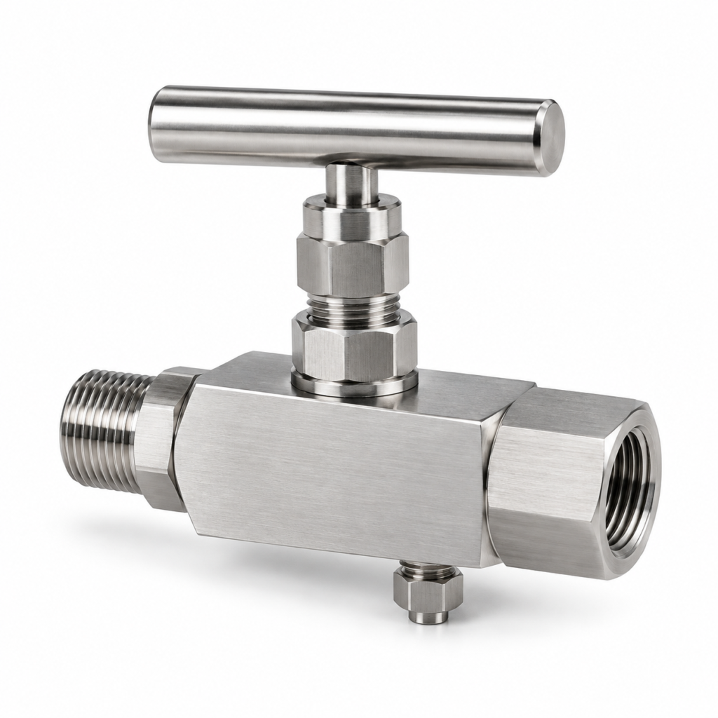
Representative image — the item supplied is sourced to the approved drawing and specification, confirmed at order.
TSI-12-003Gauge Isolation Valve with Vent / Bleed
Compact bar-stock isolation valve with a single 1/4 in. vent or bleed port. Isolate the instrument, open the port to release trapped pressure, then remove or calibrate the instrument.
| Size | Inlet 1/2 in. male NPT; outlet 1/2 in. female NPT (reference); vent port 1/4 in. female NPT |
|---|---|
| Pressure | Up to 6,000 psig (414 bar) at 100°F (38°C) in 316 stainless steel; selected designs 10,000 psig (690 bar) |
| Temperature | PTFE packing to 450°F (232°C); graphite packing to 1,000°F (538°C) on selected designs |
| Body material | 316 / 316L stainless steel; other alloys on request |
| Orifice / Cv | Approx. 4.0 mm to 5.4 mm; Cv approx. 0.35 to 0.46 where published |
| Tip / packing | Metal-to-metal tip; PEEK soft tip on selected designs; PTFE or graphite packing (graphite packing and a PEEK tip are not combined on some ranges) |
| Vent port | Open, or fitted with blank plug or bleed plug |
| Handle | Straight bar (T) handle |
CRising-Plug Gauge Valves
A soft-seated plug lifts clear of a straight-through flow path that can be cleared with a rod, which suits dirty, viscous or blocking media and erosive services where a small needle orifice would clog. The body has an instrument outlet and two gauge ports. The seat material, not the body, usually sets the pressure and temperature limit.
Family reference data: pressure, temperature, sizes, materials and testing
| Working pressure | Up to 6,000 psig (414 bar) at 100°F (38°C) on selected seat and body combinations. Rating falls steeply as temperature rises, and soft seats (PFA in particular) are rated well below the body. The curve for the seat, body and model supplied is confirmed with the quotation. |
|---|---|
| Temperature | Acetal seat to 250°F (121°C) for general service, 200°F (93°C) for water and steam; PEEK seat to 450°F (232°C), and higher on some designs; PFA seat has the lowest pressure rating. |
| Flow path | Straight-through and roddable; orifice approx. 6.4 mm (0.25 in.) on 1/2 in. designs, Cv approx. 1.65 to 1.8 |
| Size | Inlet 1/2 in. or 3/4 in. male NPT; outlet 1/2 in. female NPT; two gauge ports 1/2 in. female NPT (1/4 in. sizes on some ranges) |
| Seat and packing | Replaceable acetal, PFA or PEEK seat; PTFE packing, with PEEK packing standard on PEEK-seat designs |
| Body material | 316 / 316L stainless steel; Alloy 400 on selected ranges |
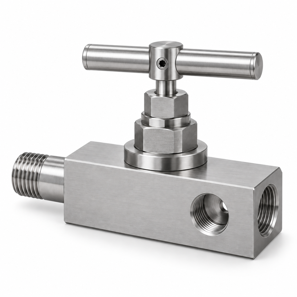
Representative image — the item supplied is sourced to the approved drawing and specification, confirmed at order.
TSI-12-004Rising-Plug Gauge Valve, Soft Seat, Roddable
Multi-port gauge valve with a soft-seated rising plug and straight-through flow path, for media that would block a needle valve. Replaceable seat; choose acetal, PFA or PEEK for the service.
| Size | Inlet 1/2 in. or 3/4 in. male NPT; outlet 1/2 in. female NPT; two 1/2 in. female NPT gauge ports |
|---|---|
| Pressure | Up to 6,000 psig (414 bar) at 100°F (38°C) on selected seat and body combinations; seat-limited and falling steeply with temperature |
| Temperature | Acetal seat to 250°F (121°C); PEEK seat to 450°F (232°C) and higher on some designs |
| Body material | 316 / 316L stainless steel; Alloy 400 on selected ranges |
| Orifice / Cv | Approx. 6.4 mm (0.25 in.) on the reference 1/2 in. designs; Cv approx. 1.65 to 1.8 where published |
| Seat / packing | Replaceable acetal, PFA or PEEK seat; PTFE packing (PEEK with PEEK seats) |
| Handle | Bar (T) handle |
DOptions and Special Service
These are requirements to state in your enquiry, not options available together on one valve. Not every combination exists in every design; TSI confirms the available combination against the manufacturer’s ordering table before quoting.
- Packing: PTFE (standard); flexible graphite for high temperature; PEEK, and UHMWPE (to 250°F, 121°C), on selected designs. Graphite packing and a PEEK soft tip cannot be combined on some ranges.
- Stem tip: metal vee or ball tip; regulating or metering tips and cobalt-alloy tips on selected designs; PCTFE soft tip (limited to 200°F, 93°C) and PEEK soft tip on selected designs.
- 10,000 psig (690 bar): available on selected designs only; the derating curve is specific to the model.
- Sour service: materials selected to ANSI/NACE MR0175/ISO 15156 on request. All wetted and pressure-containing parts must be checked, not only the body.
- Oxygen cleaning: cleaning to ASTM G93 Level C on request. Cleaning does not by itself approve a valve for oxygen service.
- Extended (lagging) inlet: for insulated lines; state the insulation thickness.
- Ports: plugs, bleed plugs and bleed valves for the gauge and vent ports; 1/4 in. or 1/2 in. port sizes by design.
- End connections: NPT as standard; BSP taper or parallel, socket-weld, butt-weld and tube-end connections on selected ranges. Tube-end and thin-wall weld ends can lower the pressure rating.
- Handles and operators: bar handle colours and anti-tamper operation on selected designs.
- Documentation: EN 10204 3.1 material certificates and other documents as stated in your enquiry.
§Choosing by Service
Starting points only. The final selection depends on the fluid, the design pressure and temperature, the material and the connections, and is confirmed against the selected model before quotation.
| Service | Start with | Check before ordering |
|---|---|---|
| Clean gas or liquid, general instrument service | TSI-12-001 | Rating at your design temperature; gauge connection thread (NPT or G 1/2 B). |
| Insulated line | TSI-12-002 | State the insulation thickness. The extension does not raise the pressure rating. |
| Instrument must be vented before removal or calibration | TSI-12-003, or a gauge port on TSI-12-001 / 002 fitted with a bleed valve | A vent port is not a second isolation barrier. Route the discharge to a safe location. |
| Dirty, viscous or blocking medium; flow path may need rodding | TSI-12-004 | The seat material (acetal, PFA or PEEK) sets the pressure and temperature limit. |
| Steam | TSI-12-001 or 002 with graphite packing | PTFE packing is limited to 450°F (232°C) and an acetal seat to 200°F (93°C) in water and steam. A siphon is normally fitted between the line and the instrument. |
| Temperature above 450°F (232°C) | Graphite packing on selected designs of TSI-12-001 to 003 | Graphite packing and a PEEK soft tip are not combined on some ranges. Confirm the pressure rating at your design temperature. |
| 10,000 psig (690 bar) | Selected designs of TSI-12-001 to 003 | The derating curve is specific to the model. Confirmed against the selected design. |
| Sour service (H2S) | Any code, by model | Materials to ANSI/NACE MR0175 / ISO 15156 on request. Check every wetted part, not only the body. |
| Oxygen-enriched service | Any code, by model | Cleaning to ASTM G93 Level C on request. Cleaning is not an approval for oxygen service. |
§Pressure – Temperature Guidance
Reference working pressures for a 316 stainless steel body with a metal-seat ball or vee tip, in psig (bar approximate). The rating of any valve we supply is the one on its manufacturer’s table for the exact model, packing and end connection.
| Temperature, °F (°C) | PTFE packing | Graphite packing |
|---|---|---|
| 100 (38) | 6,000 (414) | 6,000 (414) |
| 200 (93) | 5,160 (356) | 5,160 (356) |
| 250 (121) | 4,910 (339) | 4,910 (339) |
| 300 (149) | 4,660 (321) | 4,660 (321) |
| 350 (177) | 4,470 (308) | 4,470 (308) |
| 400 (204) | 4,280 (295) | 4,280 (295) |
| 450 (232) | 4,130 (285) | 4,130 (285) |
| 500 (260) | not rated | 3,980 (274) |
| 600 (316) | not rated | 3,760 (259) |
| 700 (371) | not rated | 3,600 (248) |
| 800 (427) | not rated | 3,460 (239) |
| 900 (482) | not rated | 3,280 (226) |
| 1,000 (538) | not rated | 3,030 (209) |
Values at other temperatures are taken from the manufacturer’s full table. The table applies to metal-seat designs only. It does not apply to rising-plug soft-seat designs, Alloy 400 bodies (typically 5,000 psig at 100°F), 10,000 psig designs or tube-end and weld-end connections.
- The usable rating is set by the weakest element: body, seat, packing, end connection or connected tubing.
- Maximum pressure and maximum temperature are not simultaneous. Check your design pressure against the rating at your design temperature.
- Soft seats and soft tips (PCTFE, acetal, PFA, PEEK) lower the rating well below the table above; PFA seats are lowest.
§Materials
316/316L is the core body material. Other alloys are supplied against the manufacturer’s model and ordering table, not by assumption.
| Material | UNS | Typical bar-stock specification | Rating note | Supply |
|---|---|---|---|---|
| 316 stainless steel | S31600 | ASTM A479, A276, A182 | Basis of the 6,000 psig rating | Core range |
| 316L stainless steel | S31603 | ASTM A479, A276, A182 | Dual 316/316L certification on some ranges | Core range |
| Alloy 400 (Monel) | N04400 | ASTM B164, B564 | Typically 5,000 psig at 100°F | On request |
| Alloy C-276 | N10276 | ASTM B574, B564 | Confirmed per model | On request |
| Super duplex | S32750 (F53) | ASTM A479 | Confirmed per model | On request |
A material listed for a range does not mean every size, pressure or temperature is available in it. In sour, chloride or other corrosive service, check every wetted part (tip, stem, seat, packing support) as well as the body.
§Standards
Standards describe threads, materials, cleaning and certificates. They do not certify a valve; conformity of a specific valve is stated by its manufacturer and confirmed for the order.
| Standard | What it covers | Use in a gauge valve enquiry |
|---|---|---|
| ASME B1.20.1 | NPT tapered pipe threads | Standard inlet, outlet and port threads |
| ISO 7-1 / EN 10226-1; ISO 228-1 | BSP taper threads; BSP parallel threads (not pressure-tight on the thread, so a face or sealing ring is needed) | On request, selected ranges |
| MSS SP-99 | Instrument valves in steel and alloy, NPS 2 and smaller, to 15,000 psi at 100°F | Reference practice for instrument valves; it does not define a single design |
| ANSI/NACE MR0175 / ISO 15156 | Materials for H2S-containing environments in oil and gas production | Sour-service materials on request, with all wetted parts checked |
| ASTM G93 | Cleaning levels for oxygen-enriched service | Level C cleaning on request; not an oxygen-service approval |
| EN 10204 | Types of inspection documents | Type 3.1 material certificate; state any other requirement |
| EN 837-1 | Bourdon-tube pressure gauges, including the G 1/2 B parallel gauge thread | Applies to the gauge, not the valve: check the gauge thread against the NPT port |
- Gauge thread: gauge ports are NPT as standard, while many gauges have a G 1/2 B parallel thread. 1/2 NPT and G 1/2 are not interchangeable; use the correct adapter and sealing ring.
- Vent is not a second barrier: a vent or bleed port releases trapped pressure but does not add isolation. Use a block-and-bleed or double block and bleed arrangement where two barriers are required, and route vent discharge to a safe location.
- Inlet pipe wall: some manufacturers require a minimum Schedule 160 pipe wall (or heavier) on the inlet fitting. Check the pipe or fitting wall thickness against the valve rating.
- Packing: a packing adjustment may be needed after commissioning or temperature cycling. Apply only the torque needed for positive shut-off.
- Weld ends: weld heat can damage packing and seat; welding must follow the manufacturer’s instructions.
- Extended body: the extension raises the handle clear of insulation; it does not change the pressure rating.
- Material and cleaning: oxygen-cleaned does not mean approved for oxygen service, and a stainless steel body does not make a valve sour-service suitable on its own.
- Type: multi-port needle (standard or extended, with insulation thickness), gauge isolation with vent or bleed, or rising-plug.
- Connections: inlet size and thread, instrument outlet, gauge or vent port sizes and threads, and the gauge thread (NPT or G 1/2 B).
- Material: body UNS grade, and any requirement for all wetted parts.
- Service: fluid, design pressure, minimum and maximum design temperature, and whether sour or oxygen service applies.
- Seat, tip and packing: metal or soft seat and seat material; PTFE, graphite or other packing.
- Options: plugs or bleed valves, handle type, 10,000 psig, tube-end or weld-end connections.
- Documentation: EN 10204 3.1 or other certificates, and any inspection requirement.
- Quantity and delivery location.
- You send the list and the service data: fluid, design pressure, minimum and maximum design temperature, body material, connections and gauge thread, and the documents you require.
- TSI reviews the requirement against the available designs, checks the rating at your design temperature and the compatibility of material, seat, packing and end connections, and raises any open point with you before quoting.
- The quotation states the design basis, the material, the rating basis and the documentation supplied, EN 10204 3.1 or as stated in your enquiry. Lead time and availability are confirmed in the quotation.
- Instrument needle valves: two-port isolation and flow regulation where no gauge or test port is needed.
- Instrument tube fittings: tube connections for the instrument outlet and impulse lines.